
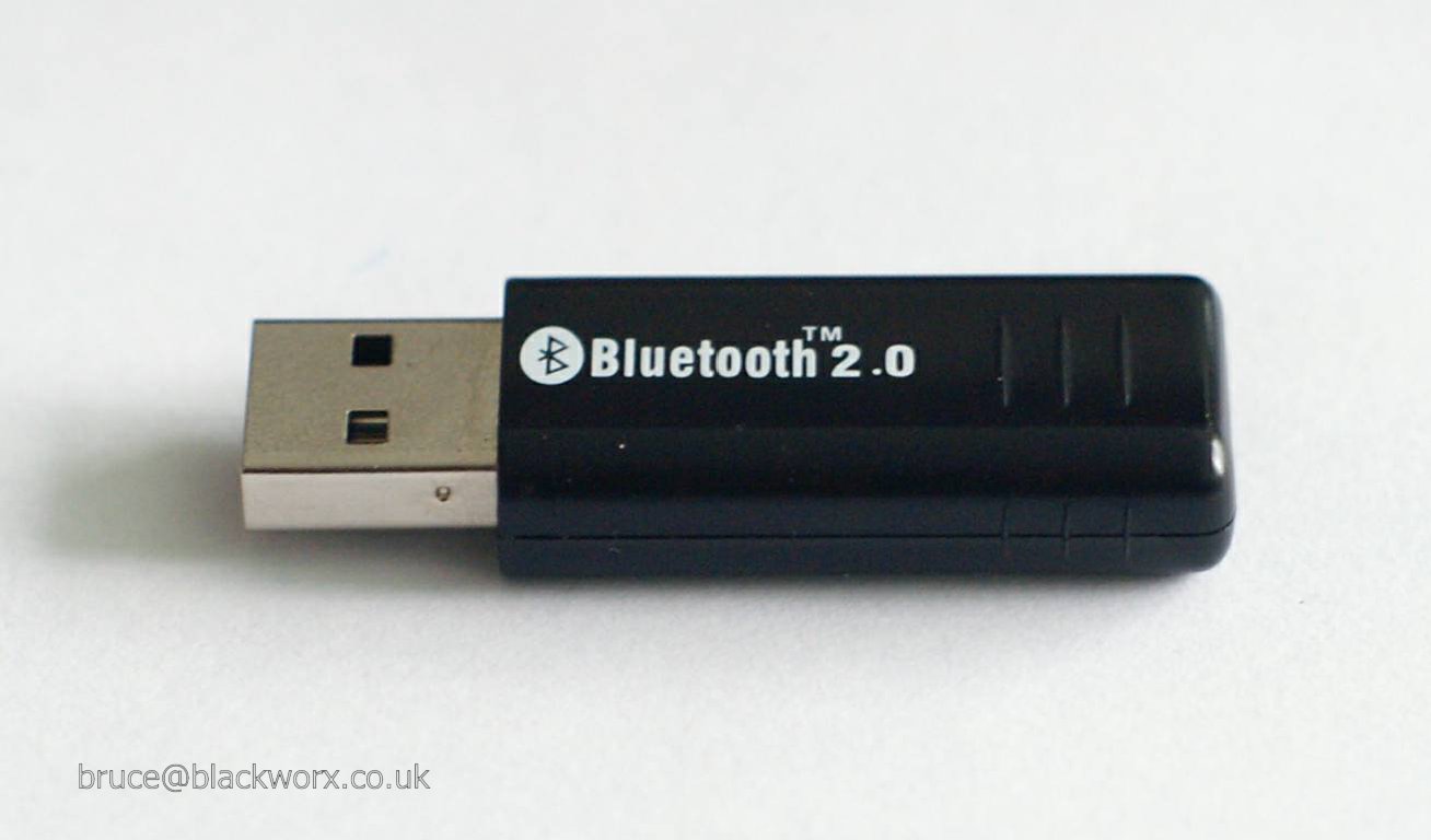
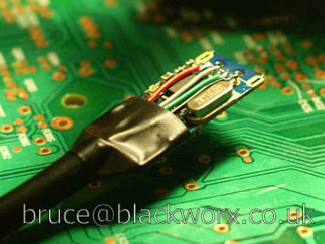
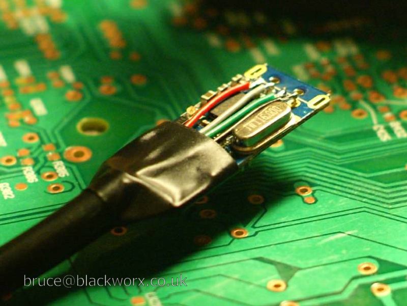
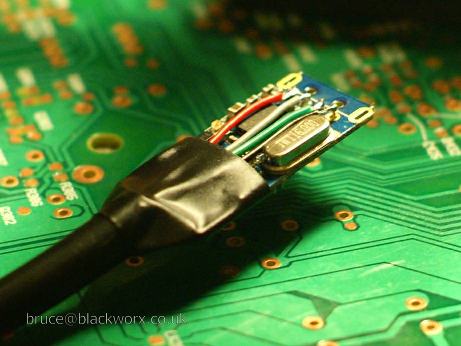
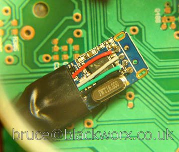
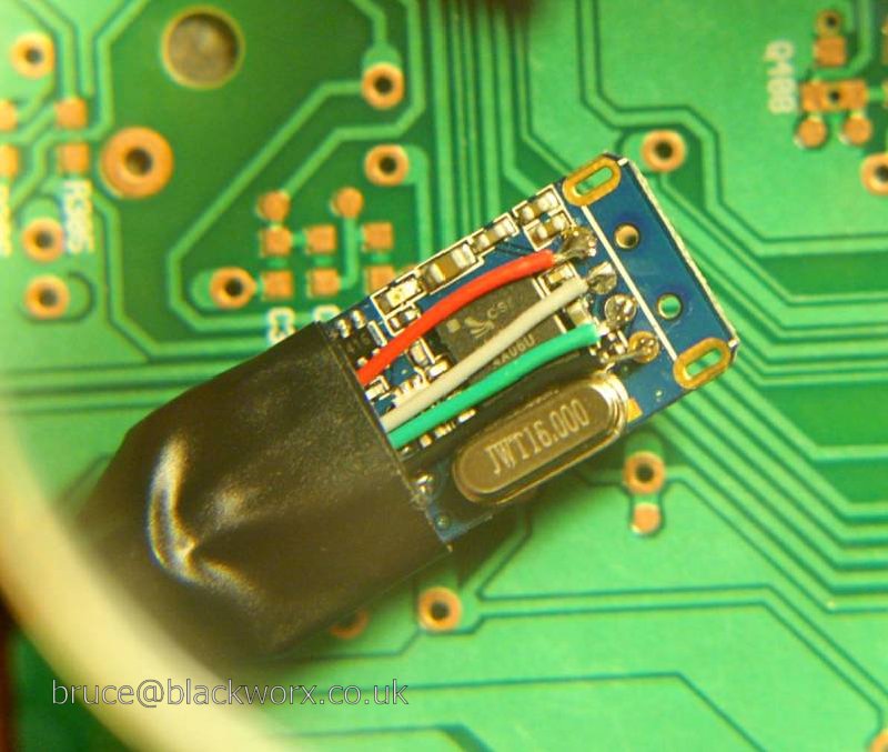
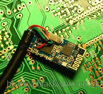
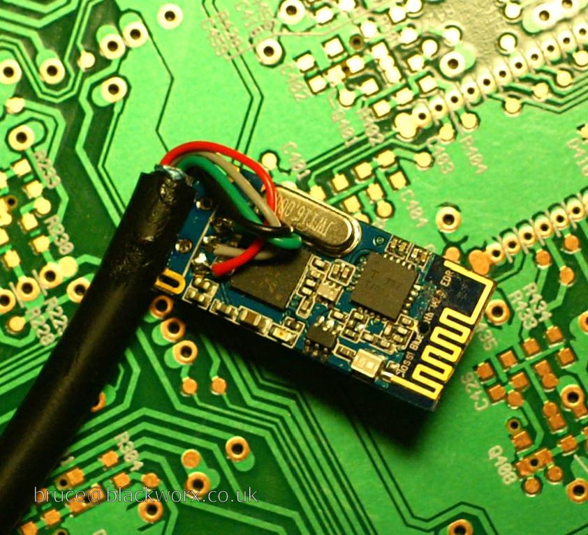
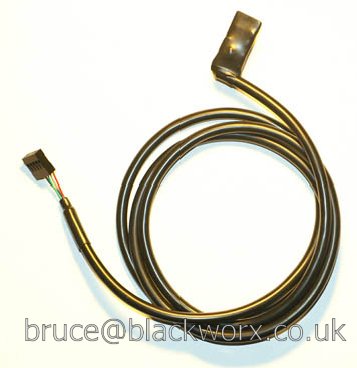
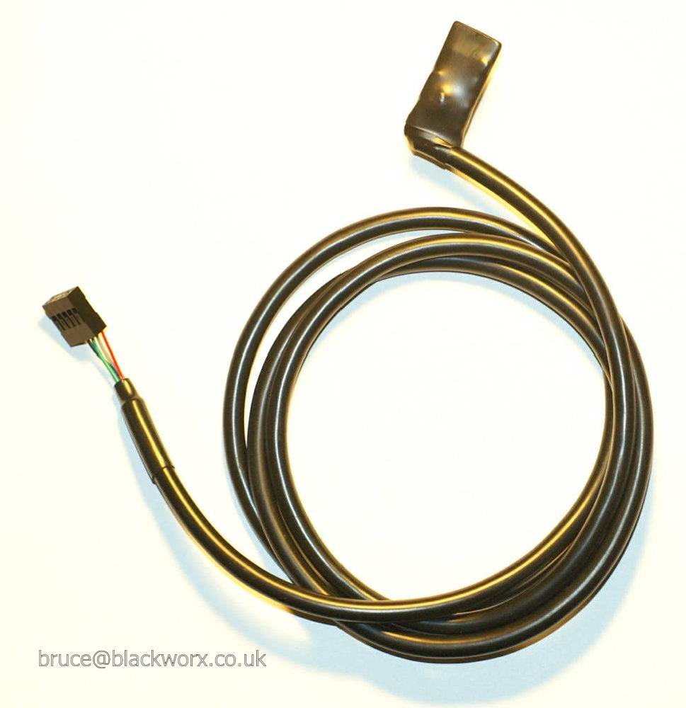
I took a £3 USB Bluetooth dongle
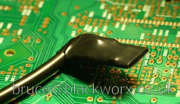
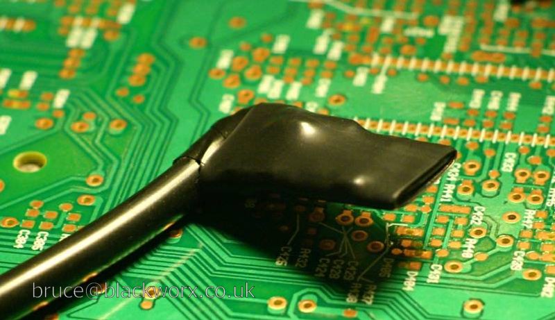
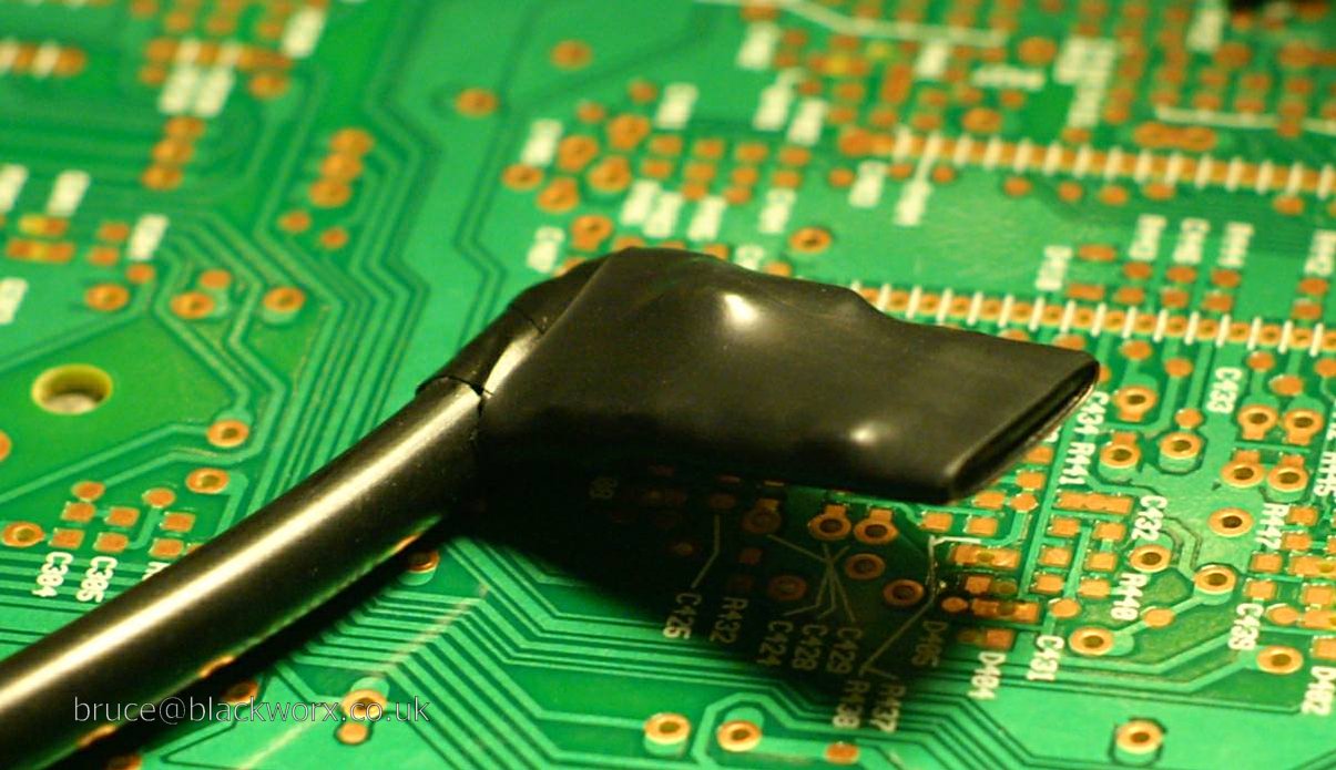
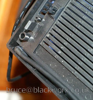
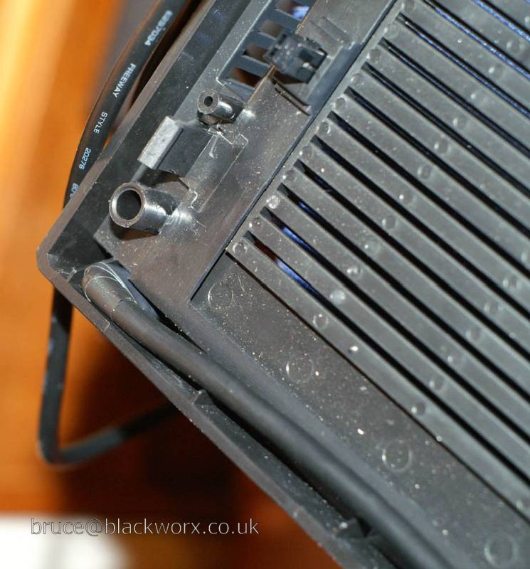
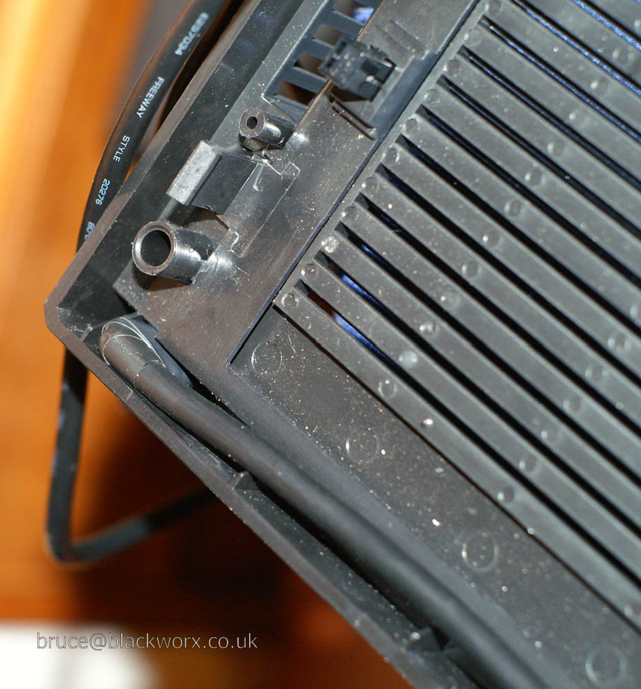
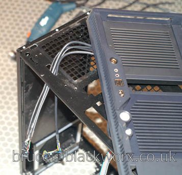
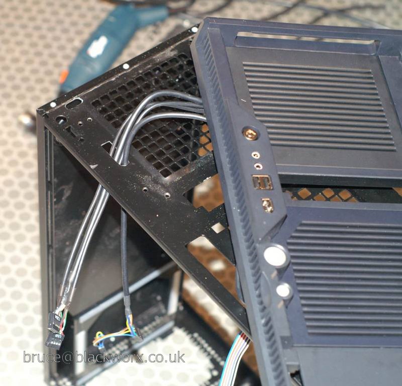
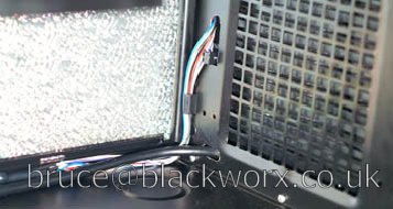
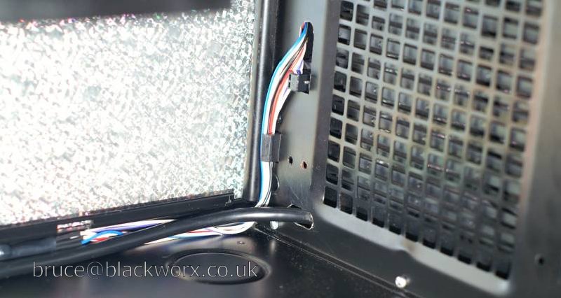
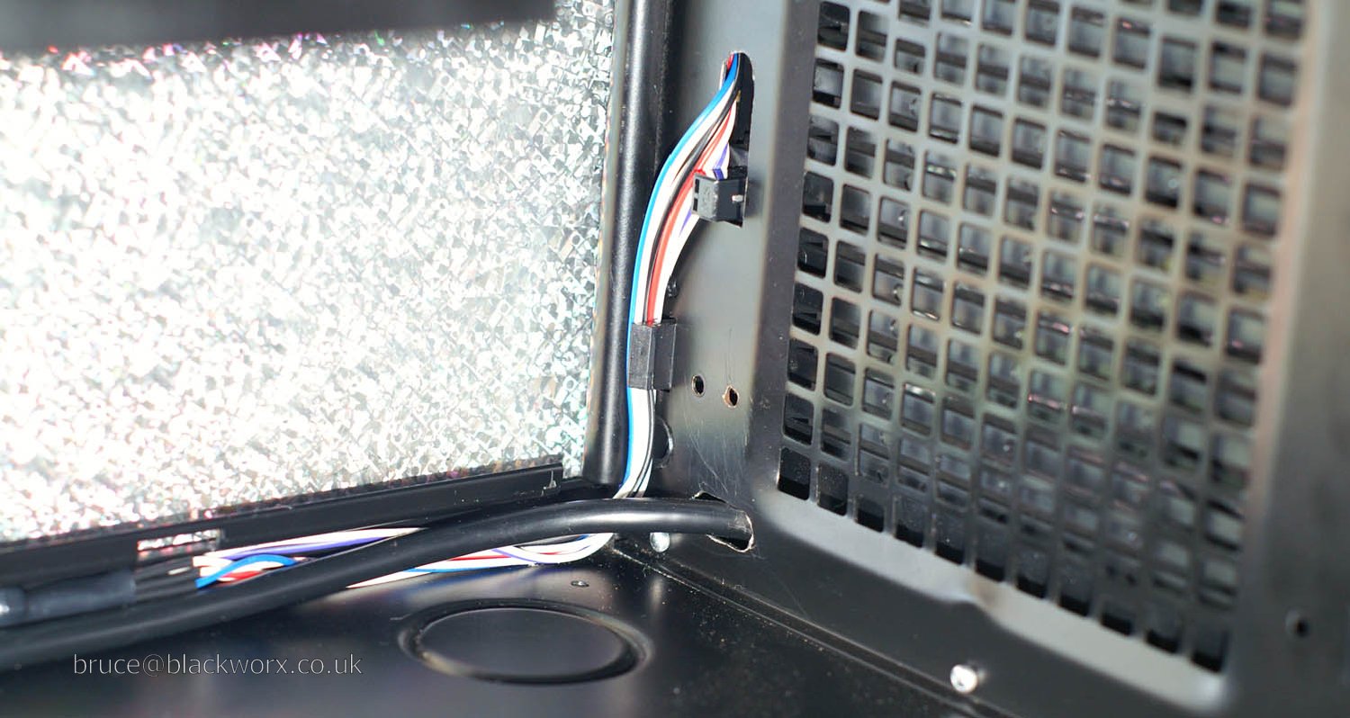
Bluetooth assembly fits in bottom corner of fascia.
Cable will be routed through a hole drilled in the front of the case. In reality I probably could've just mounted the dongle straight onto the motherboard header, but where's the fun in that? Also the case itself would probably be quite a good RF shield which is not exactly desirable.
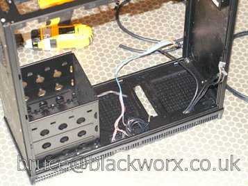
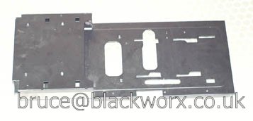
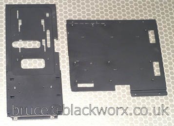
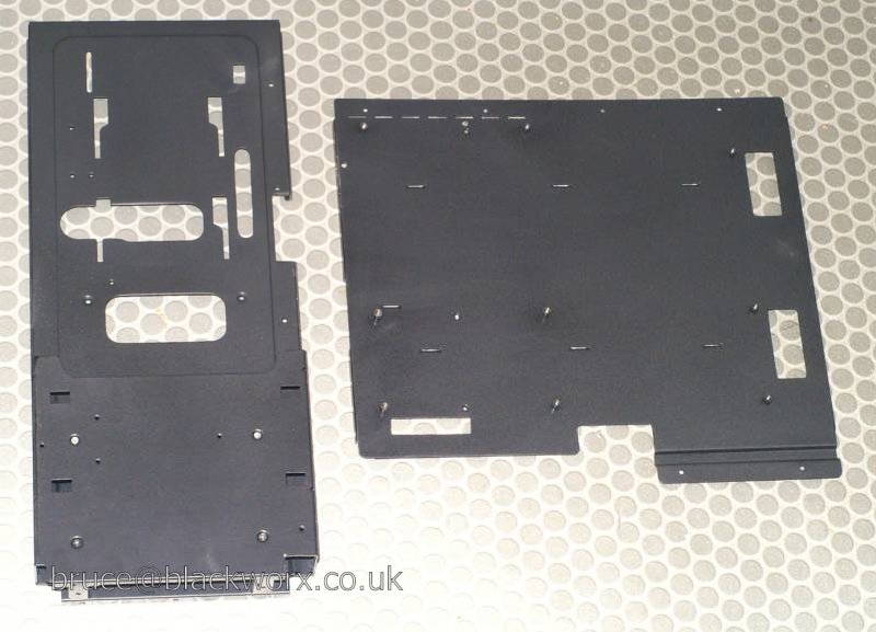
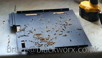
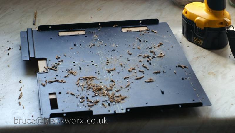
Modified the partition with two extra holes which will be next to the edge of the mobo. The big one is for front panel, USB, Bluetooth connectors and the small one to the right is for the front panel audio. Also cut the corner off right hand of front edge (bottom left in this pic) for new cable routing of front panel USB and audio.

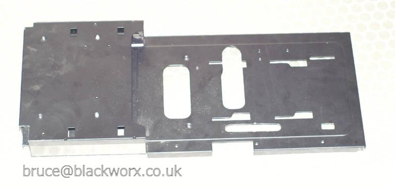
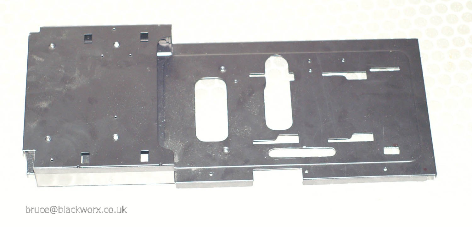
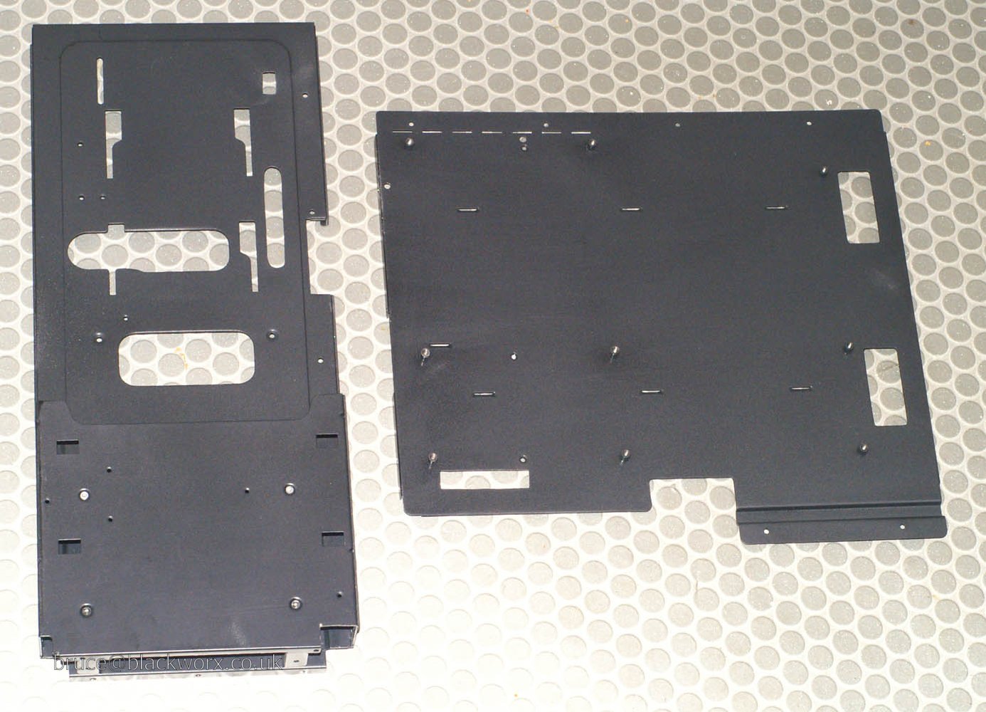
Partition and mobo tray, after repainting.
Despite my complaints about Antec's duff powdercoat job, I have to admit my spraying attempt was pretty poor. Luckily these parts will be covered up almost entirely.
I also bent the mobo while cutting the hole for the SATA leads and had to hammer it back into shape.
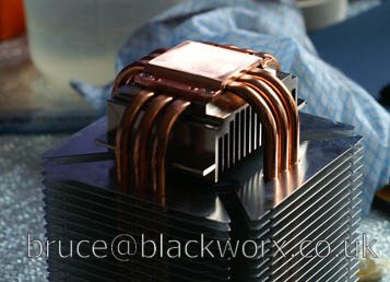
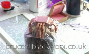
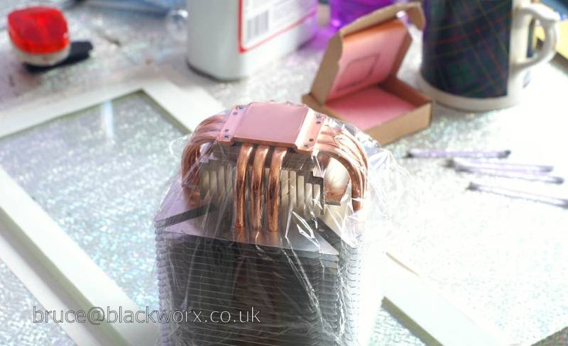
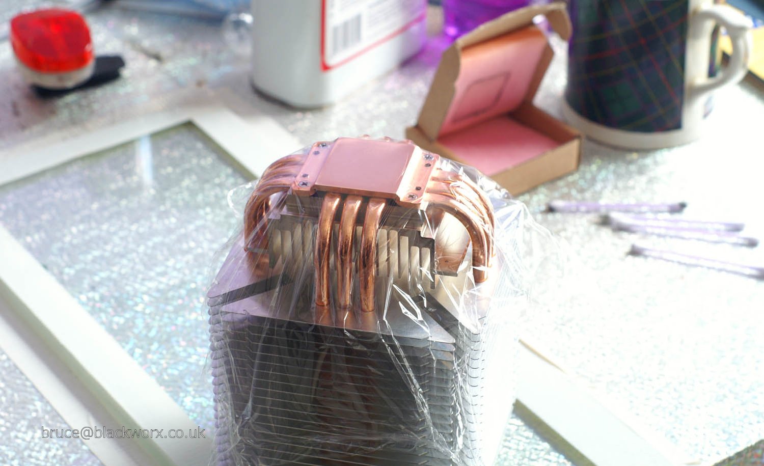
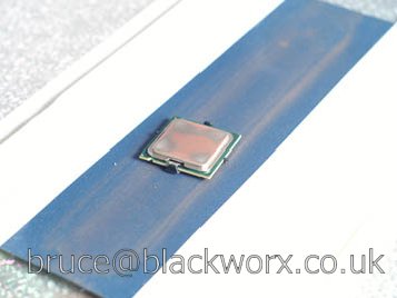
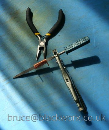
Taking a break to lap HS and CPU. This is what happens when you don't pay absolute attention. For anyone planning to lap a Ninja, be warned it is a total pain in the arse. I stupidly started off holding the fins but soon realised this was possibly not the best way to get a flat finish.
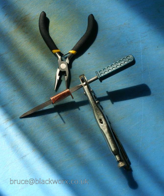
Holding as close to the base as possible produced a good, but not perfect, result.
Sidenote: whoever came up with the nickname "Minja" for the mini Ninja is an unsung genius. I don't know what the first syllable connotes in N.Amer. English, but over here it's considered a bit, er, lippy.
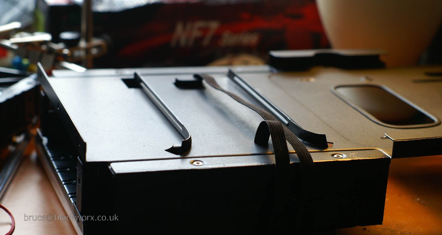
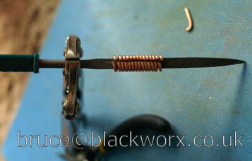
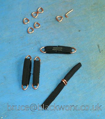
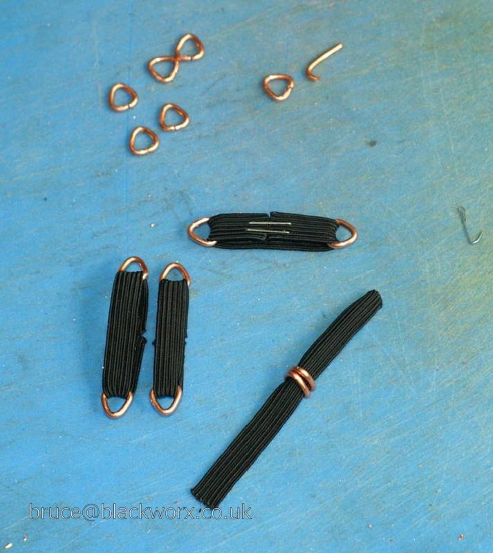
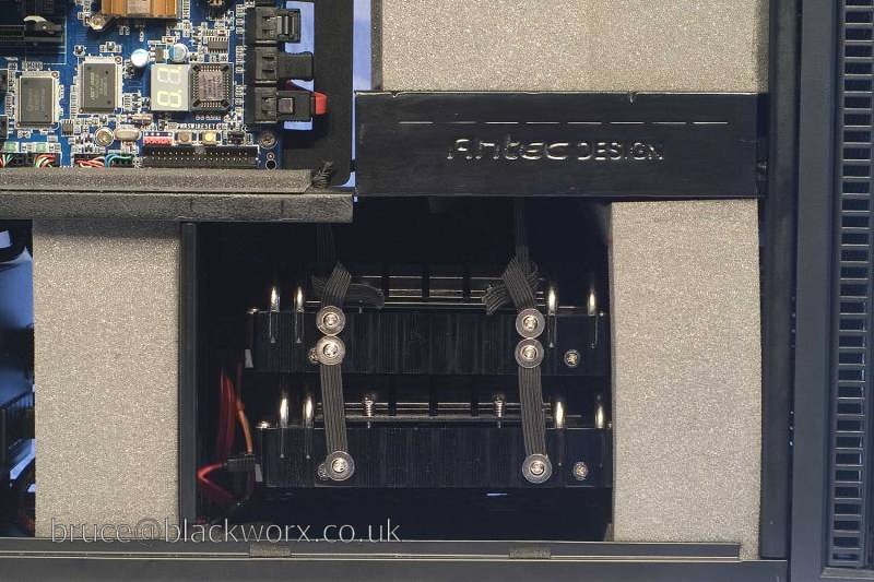
Elastic straps. Yes, those are staples holding them together and yes, they do work. I started off trying to stitch the elastic together, but I quickly learned that anything more than sewing on a button is beyond my abilities!
I later realised the one on the left was way too big, d'oh..
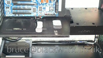
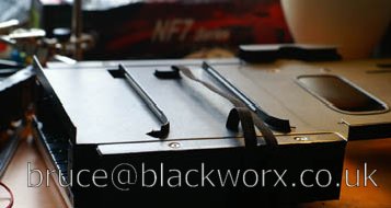
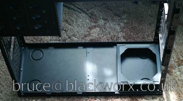
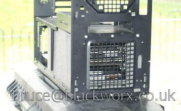
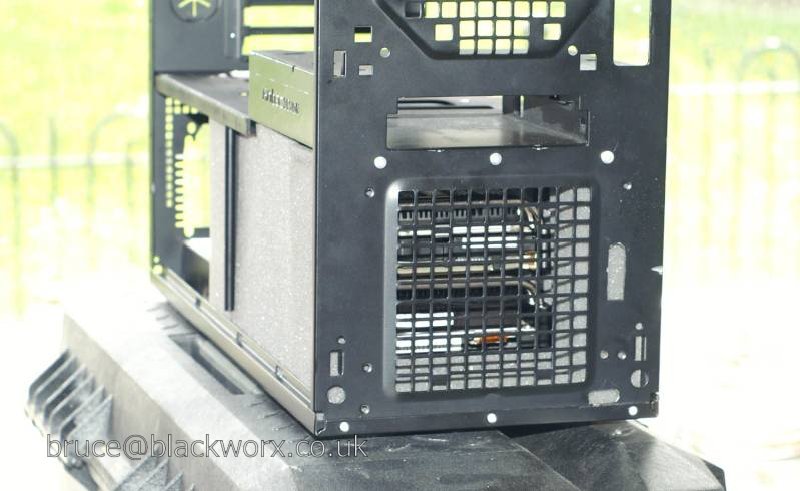
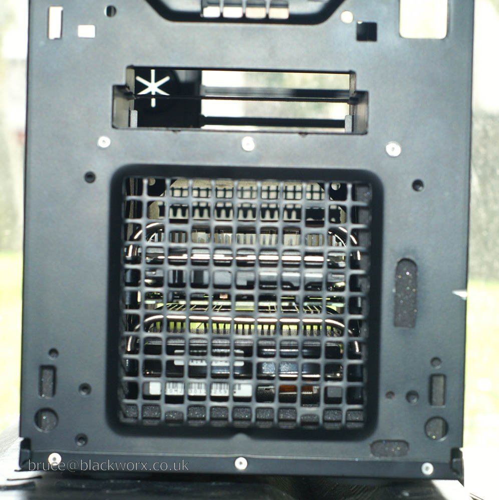
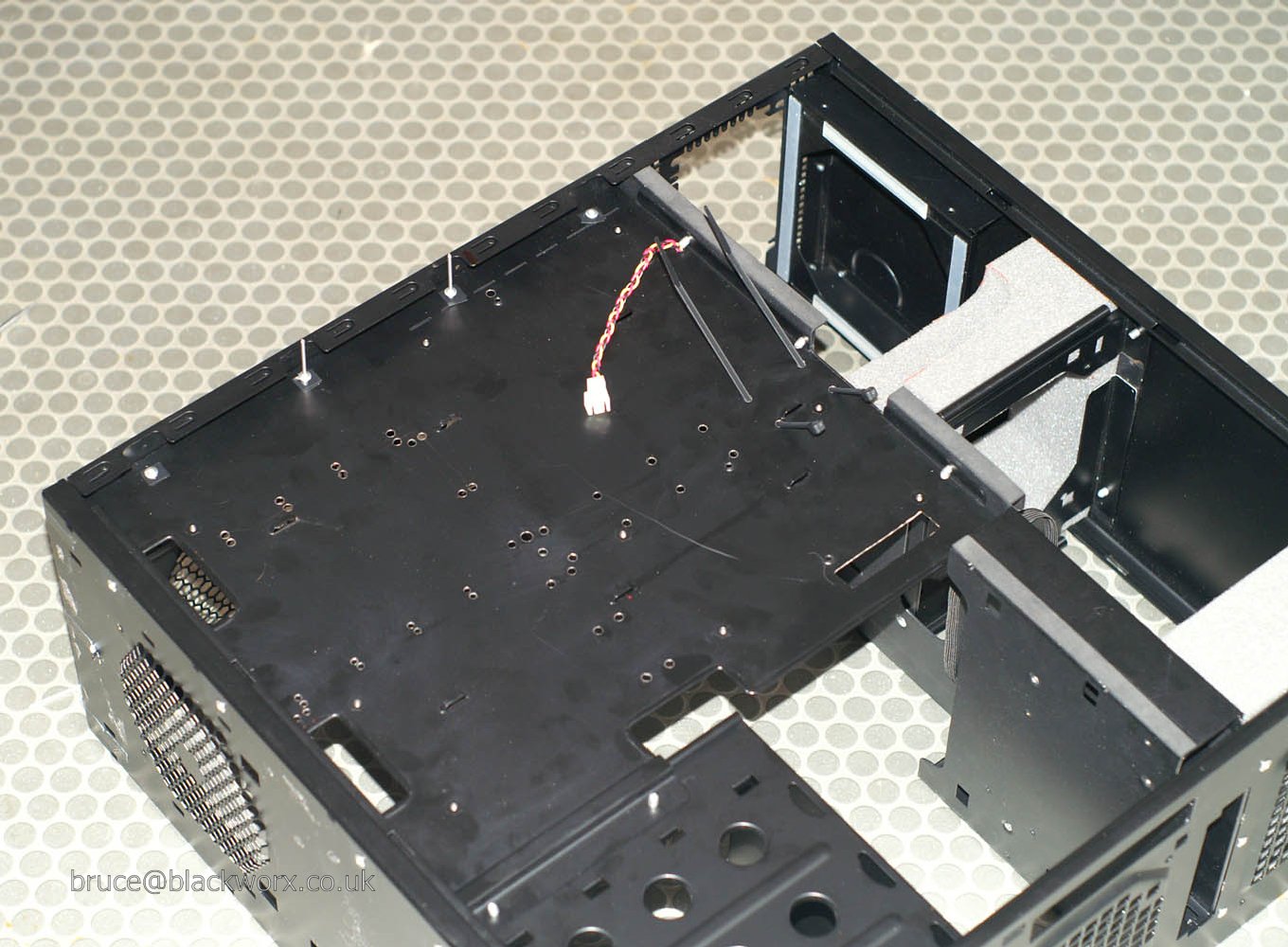
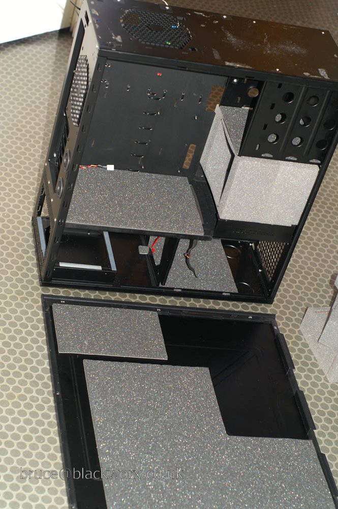
Rebuilding the case. I added some strips of electrical tape to raise the lower chamber fan mount slightly once the whole thing is put back together. I have noticed on this case (as well as others' photos around the net) that the factory assembly results in a slight downward bend in the partition. 4 strips of tape worked fine to alleviate this.
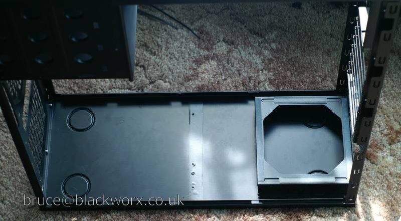
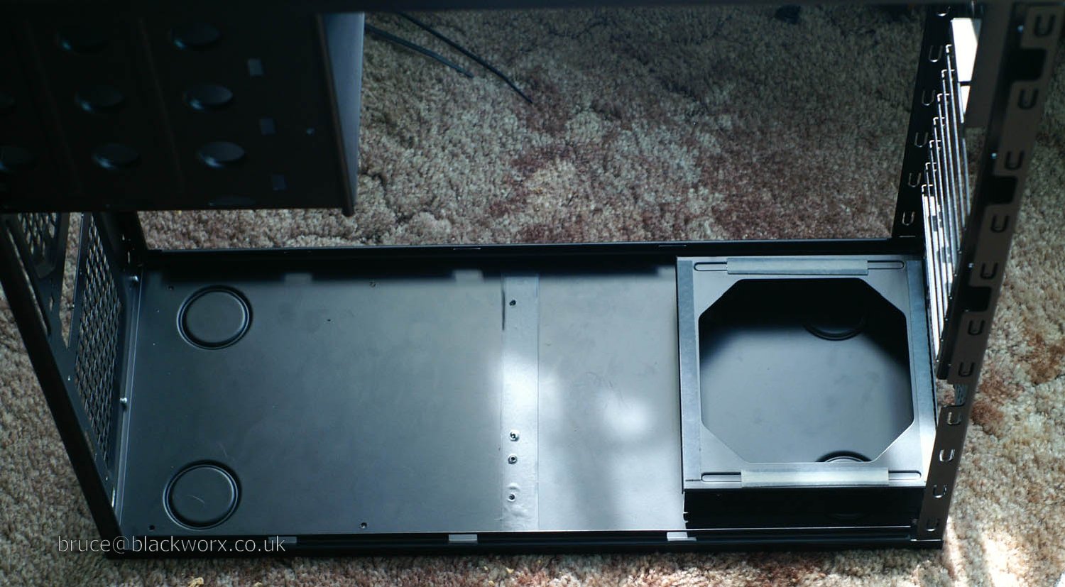
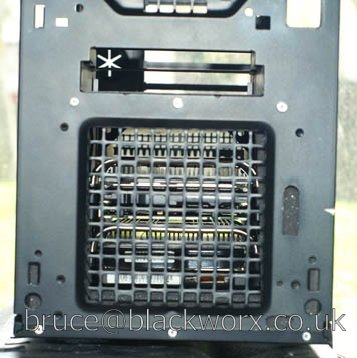
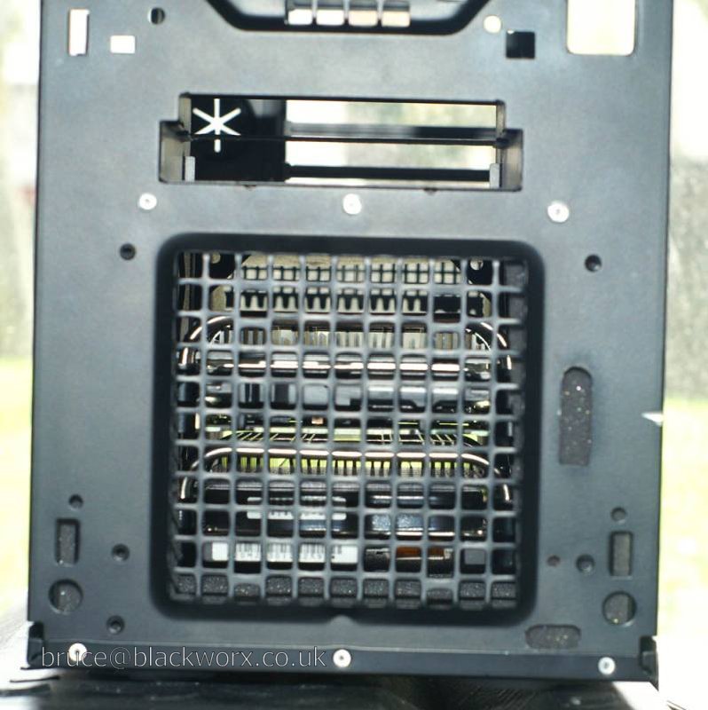
The partition is now riveted back in place, with rivets that are not loose. Take note Mr. Antec.
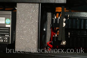
Also testing out HD chamber/suspension. Thanks to abirdie4me for the inspiration for the drive suspension.
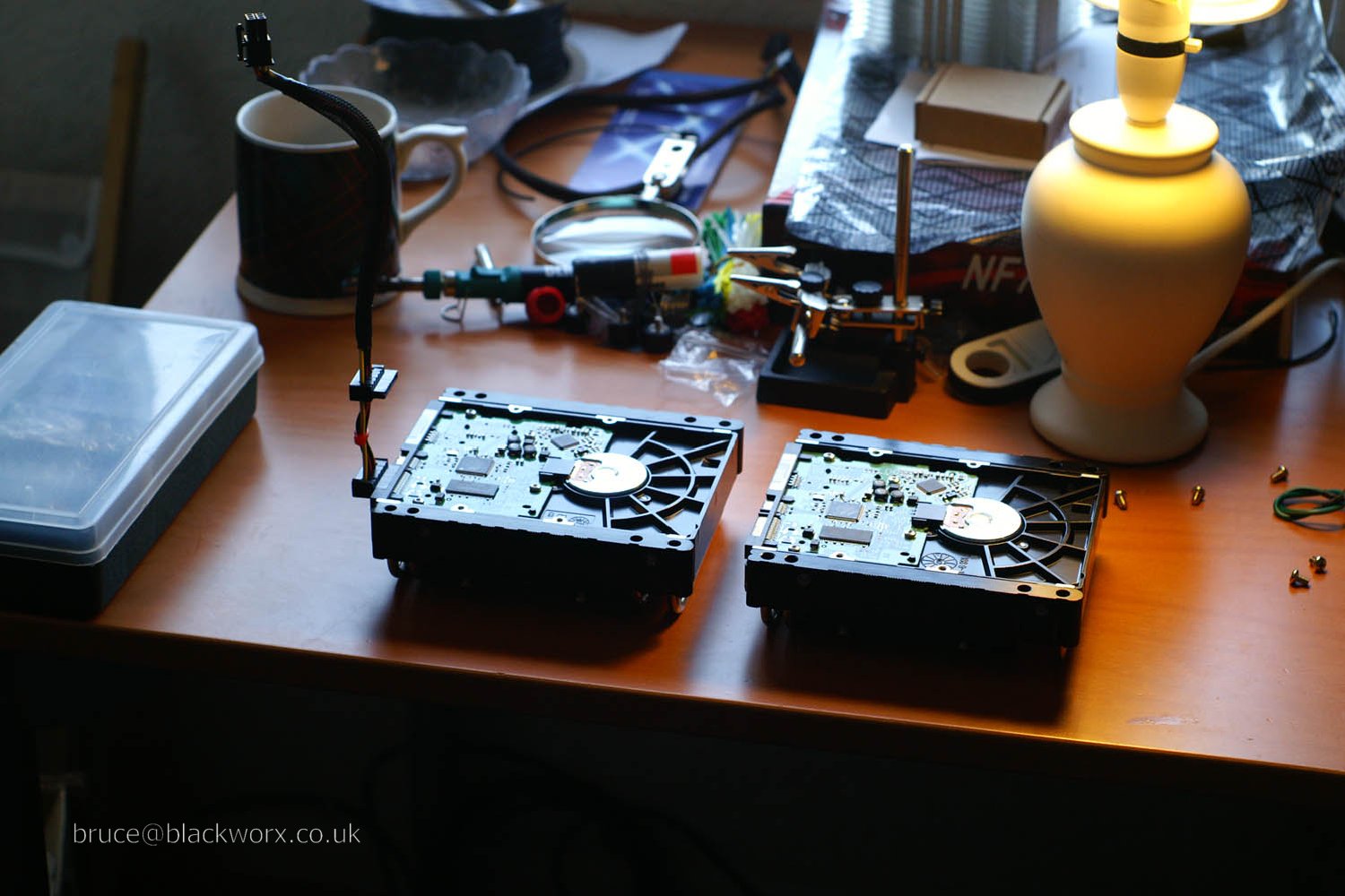
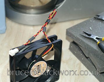
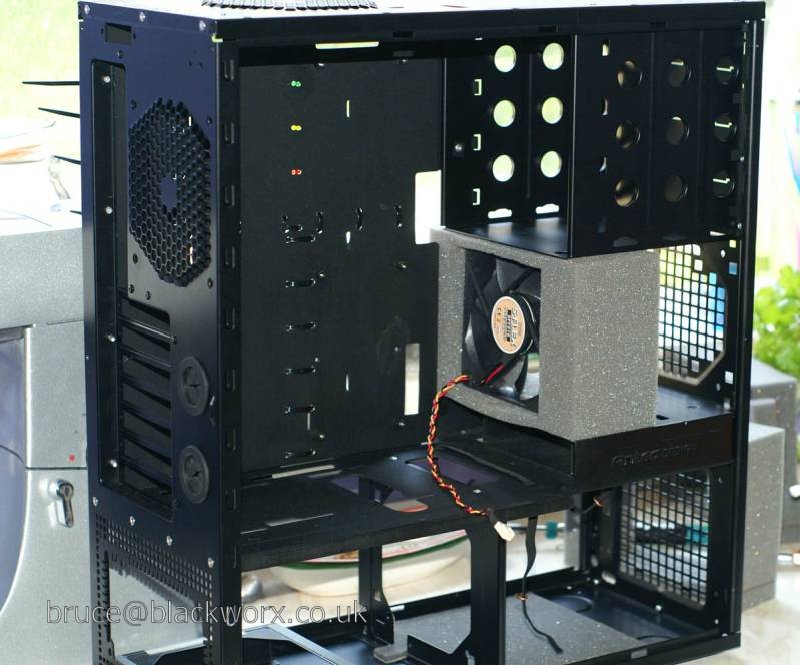
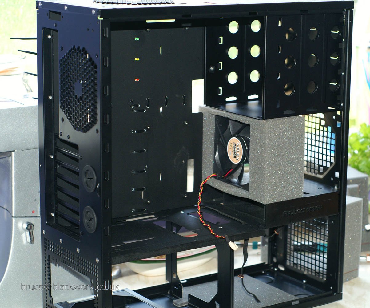
I am using Xilence Iceboxes to provide extra cooling for the hard drives. In their standard configuration (mounted in a 5.25" bay with hard rubber "vibration-reducing" bolts more commonly found in big machinery) they have little silencing benefit, but they certainly are very good at cooling, which is what I'm interested in.
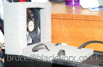
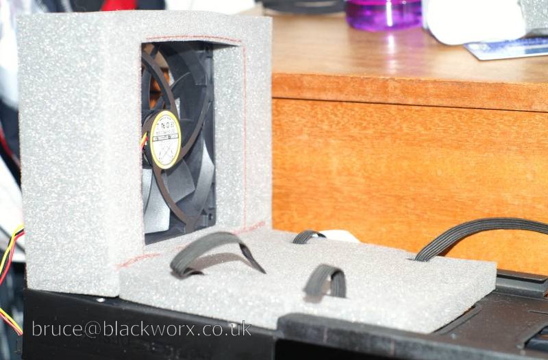
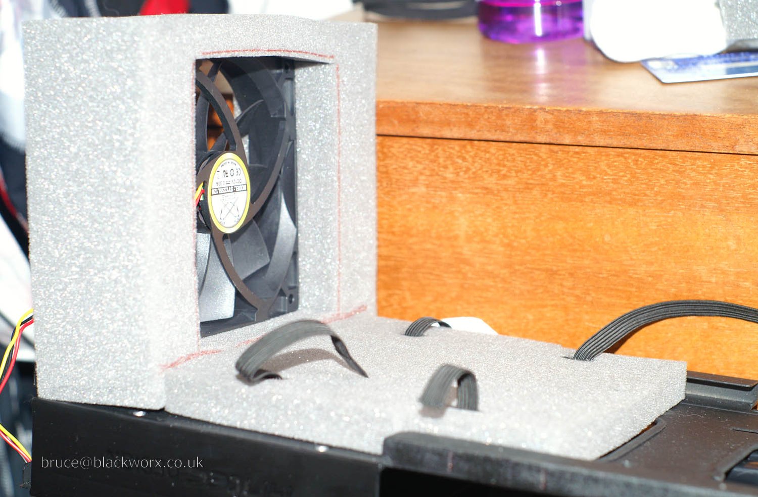
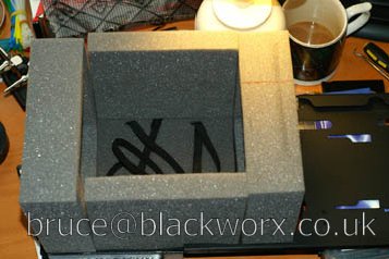
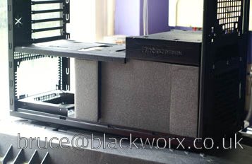
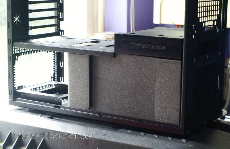
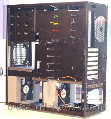
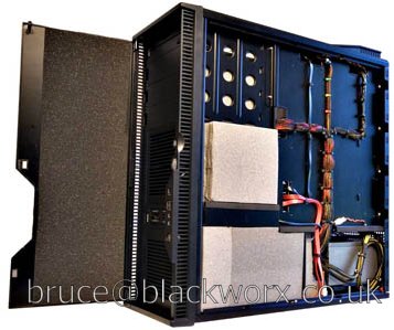
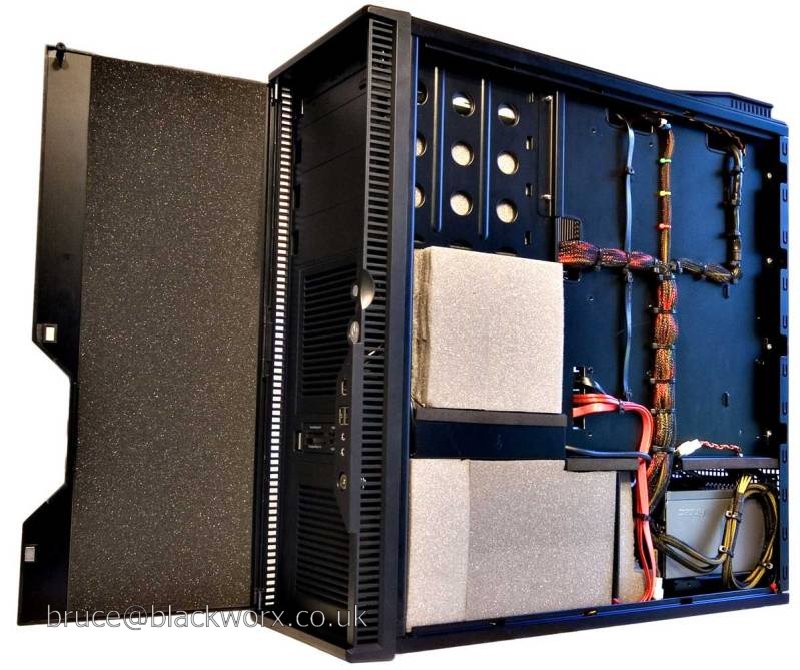
Foam chamber (like stone chamber, only softer*). The foam is supposedly 32kg/m3 acoustic foam, but I wouldn't be able to tell it apart from pick 'n' pluck foam and tbh I doubt it makes much difference on this scale. The foam side panels are there to provide a bit of extra acoustic barrier and high frequency absorption. The front and rear panels are for mounting intake/exhaust fans.
* Sim Ronan has no time for foam chamber.
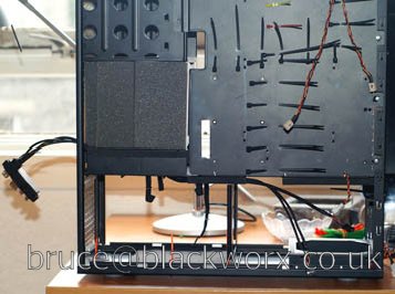
(No big pix as this one is out of focus)
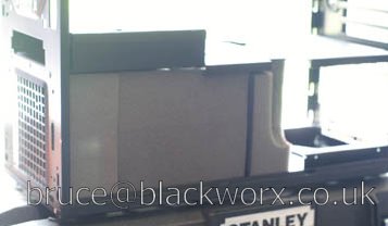
Backside


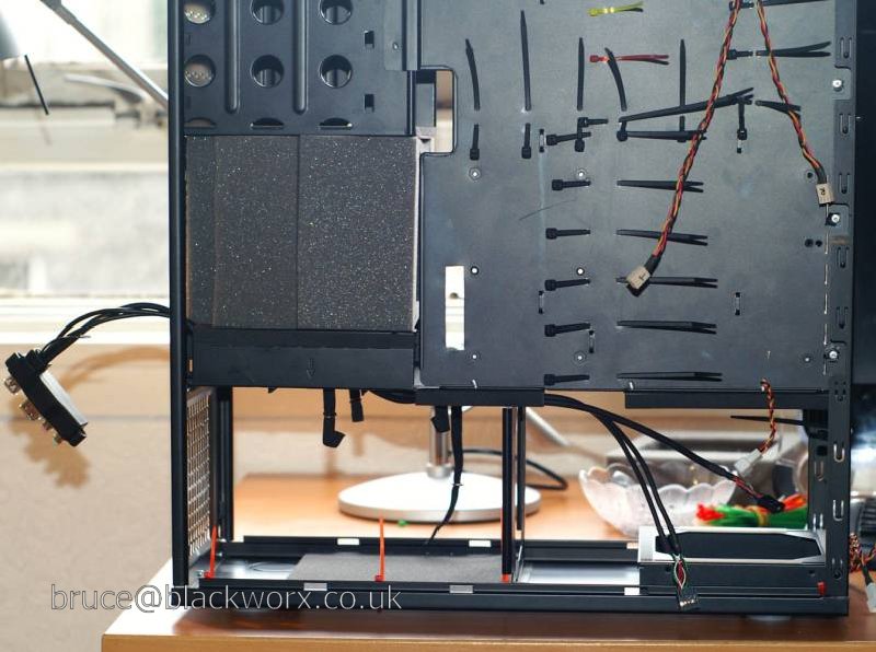
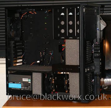
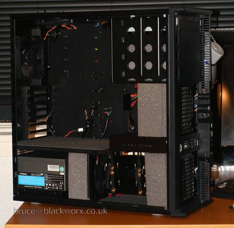
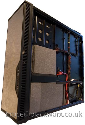
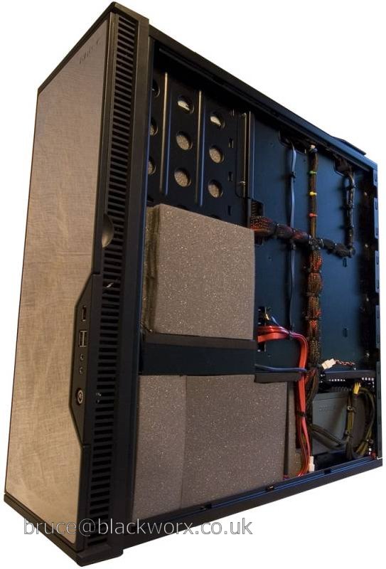
Added Acoustipack... The strip on the chamber partition is mostly to cover all the holes rather than for soundproofing, but any extra damping weight there can only be a good thing.
Also added extra block of foam in front of the main chamber intake. This is identical to the other piece and will ensure all air comes in through the front panel filter instead of being recycled case air.
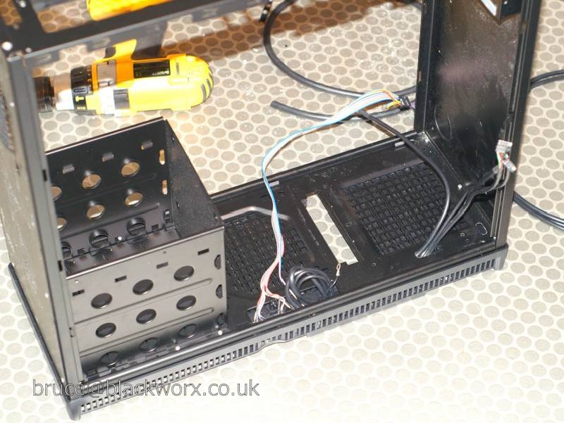
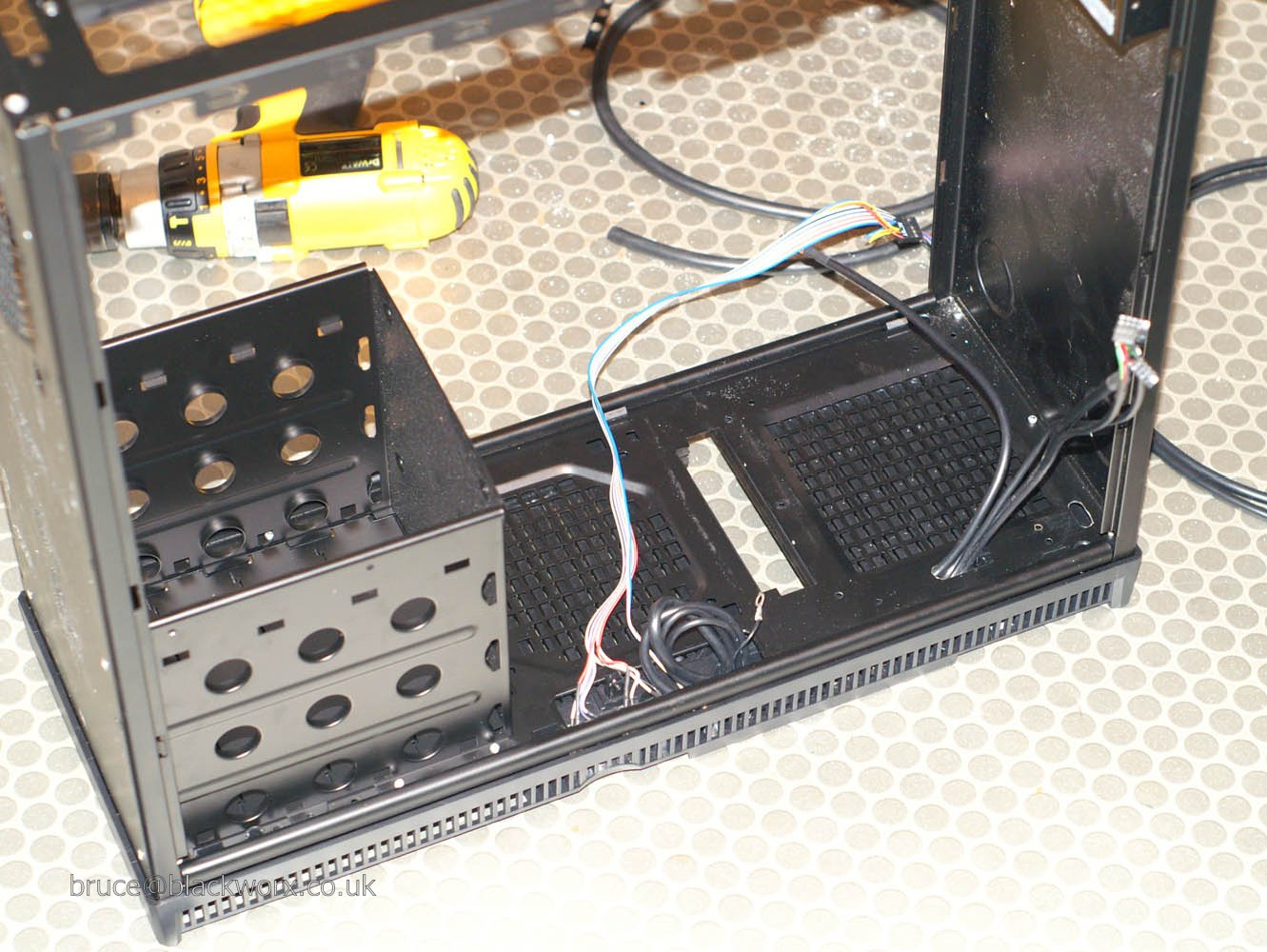
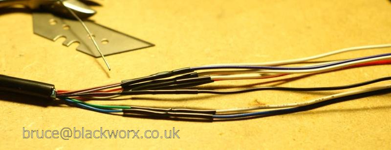
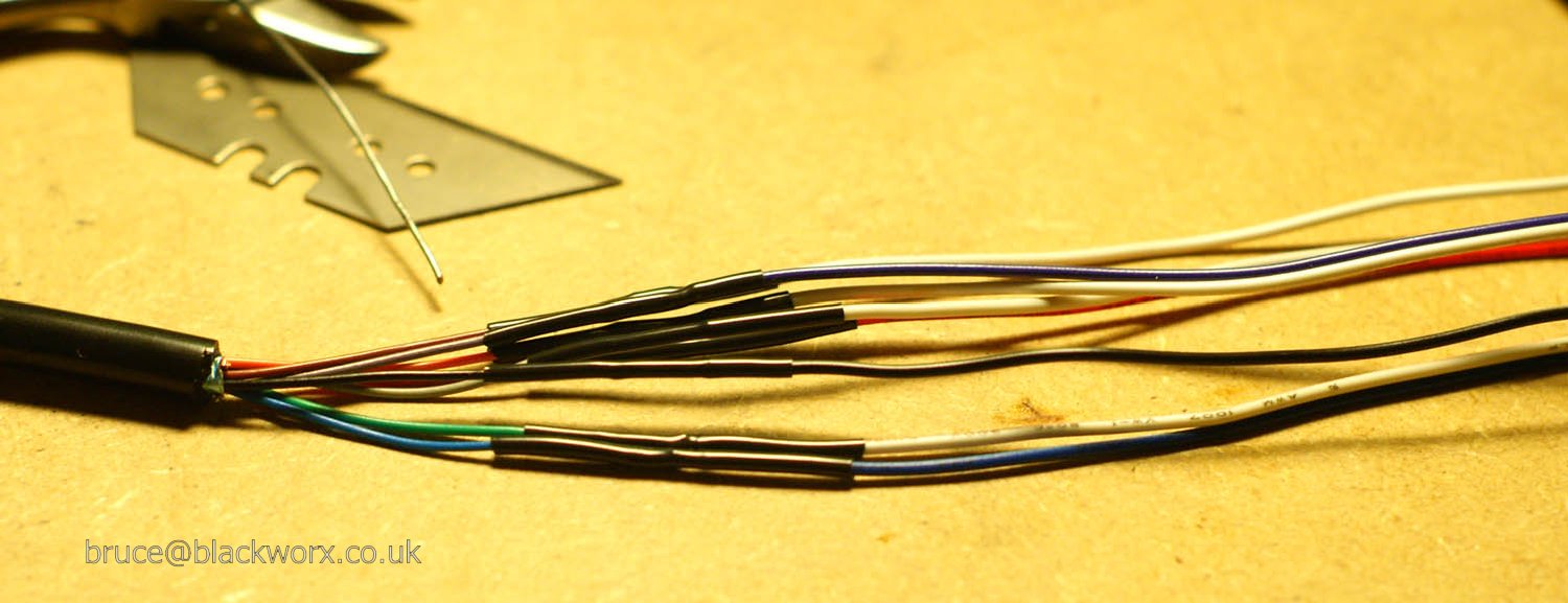
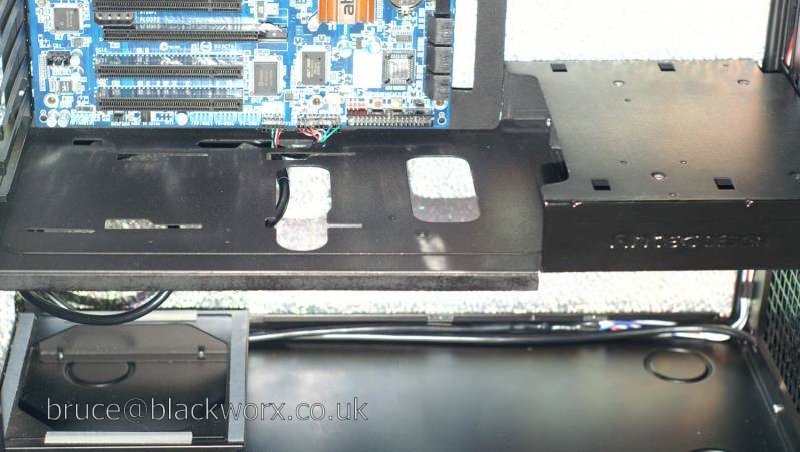
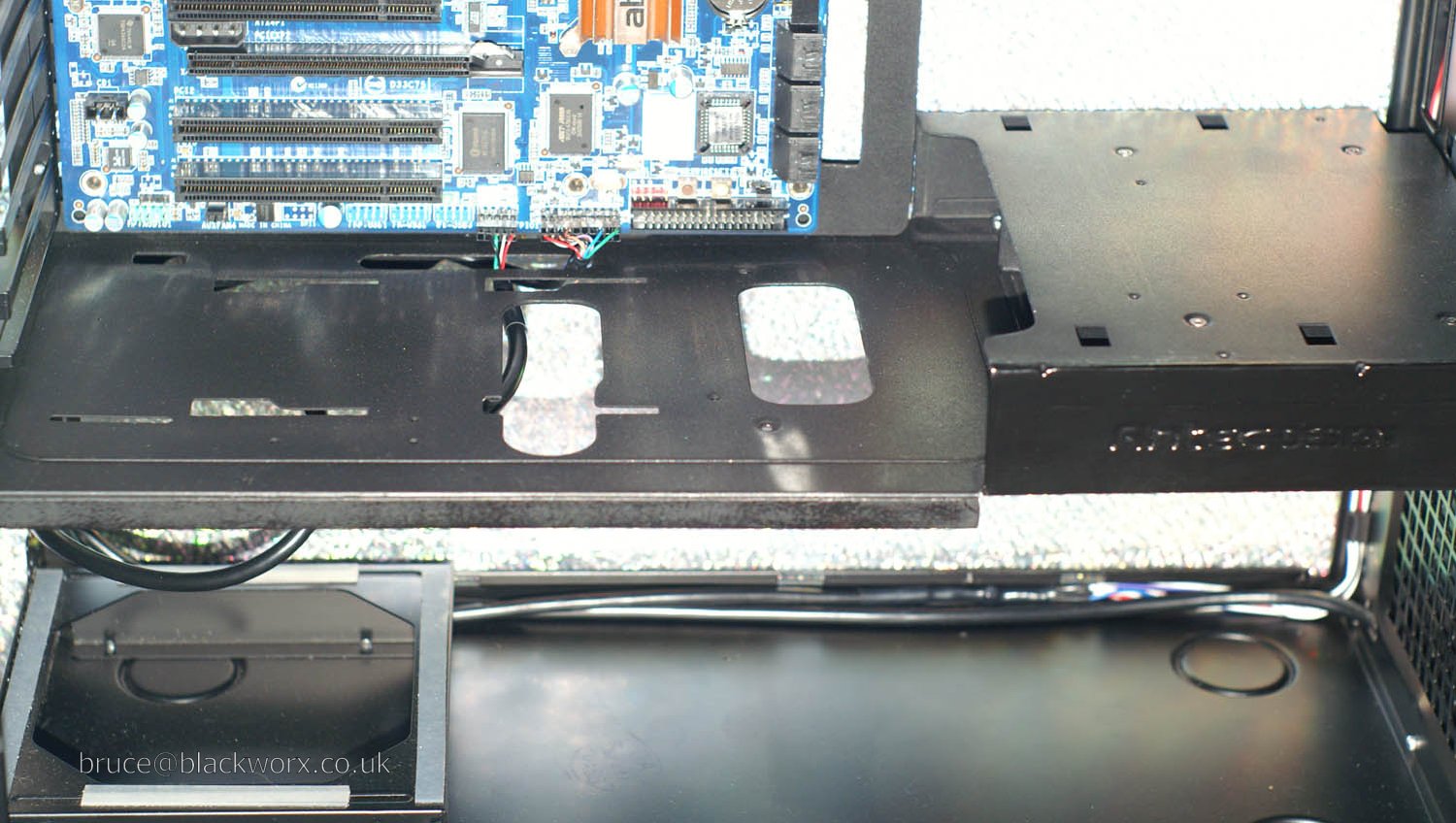
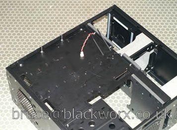
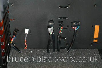
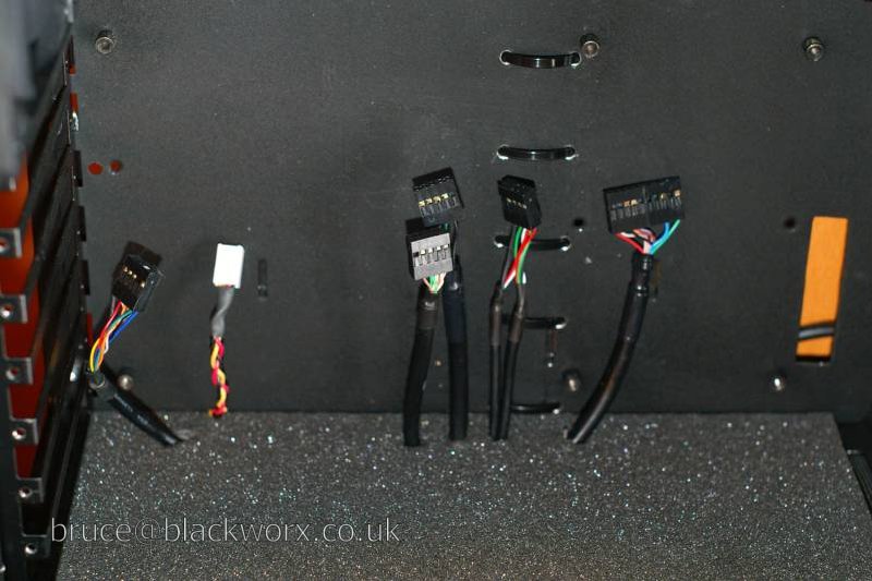
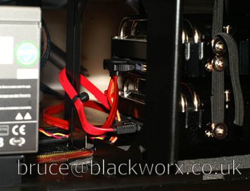
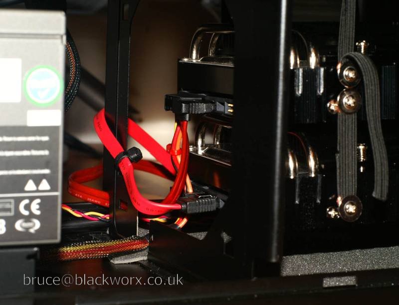
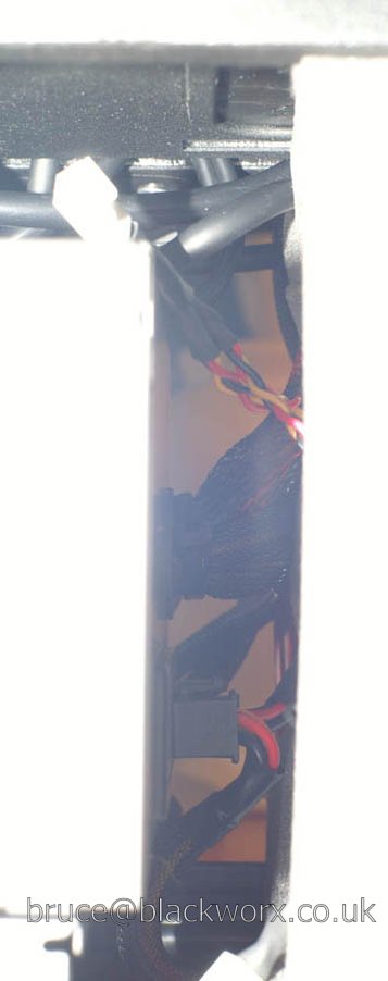
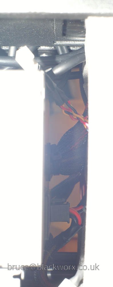
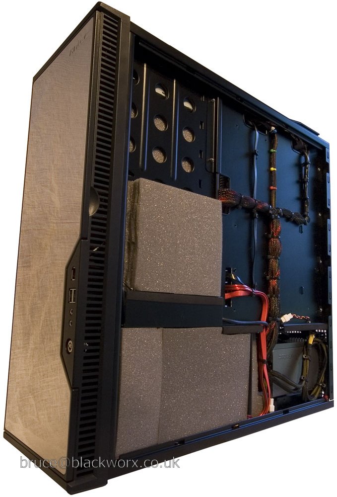
This is how I decided to route the front panel USB/audio cables instead of taking them along the bottom of the lower chamber. They go down the channel to the side of the floppy drive bay then through a hole and along the structural channel in the underside of the partition.
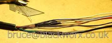
I completely removed the Firewire cable. I was originally going to keep it, but extending it would've been too much hassle. The cable itself has individually-screened pairs and an overall screen. In short, it's a mess of Mylar and polythene. If I owned or intended to buy any Firewire gear I might've gone to the effort, but as it stands there is little point. If I do end up needing Firewire, I can just attach the rear bracket supplied with the mobo.


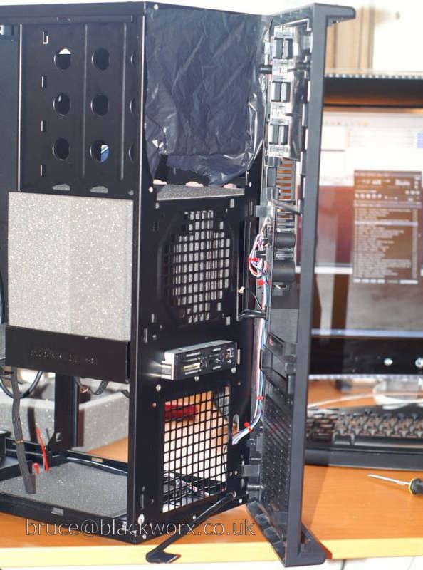
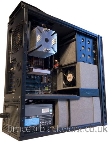
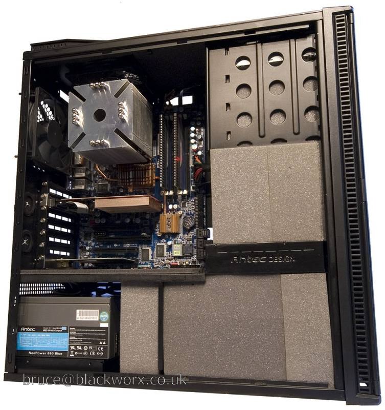
Everything's in now except the boards, intake filters and doors. I have modded the upper door to decrease intake restriction, but not the lower one. Thanks to Mr. B and others for that tip.
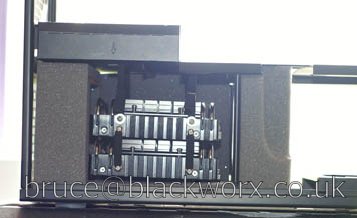
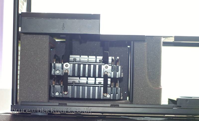
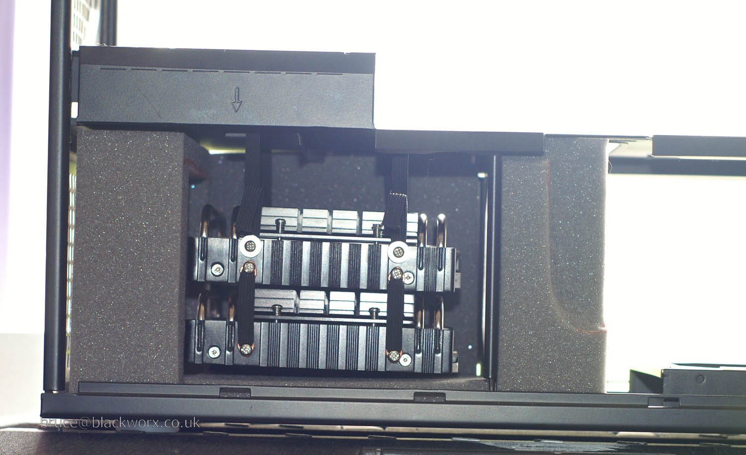
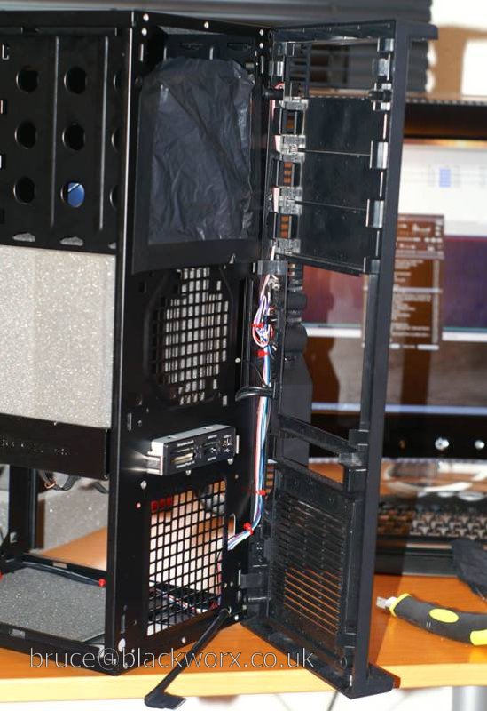
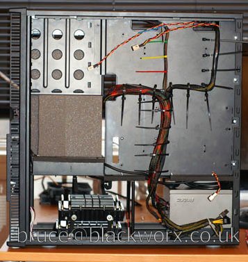
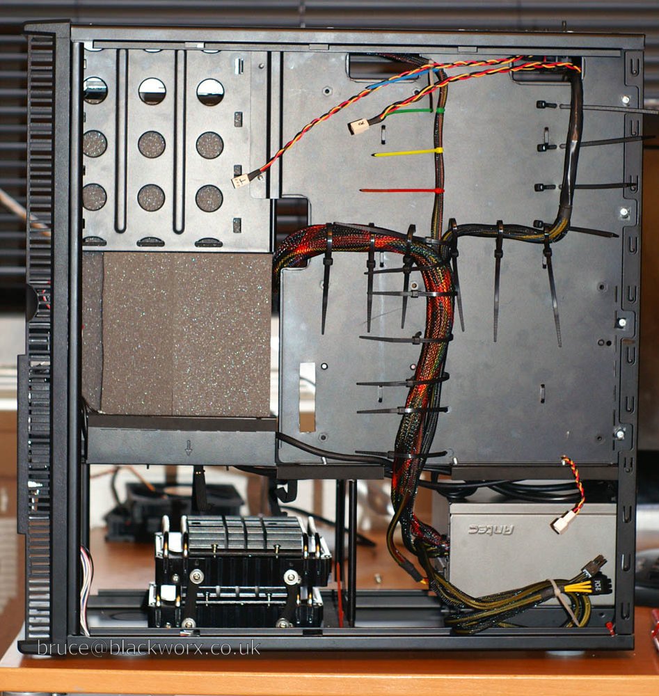
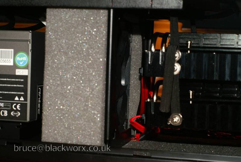
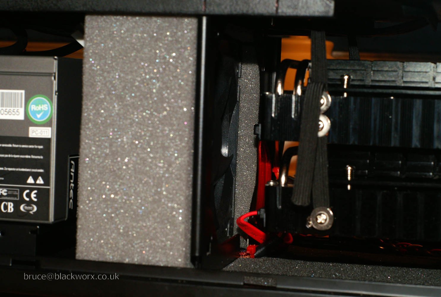
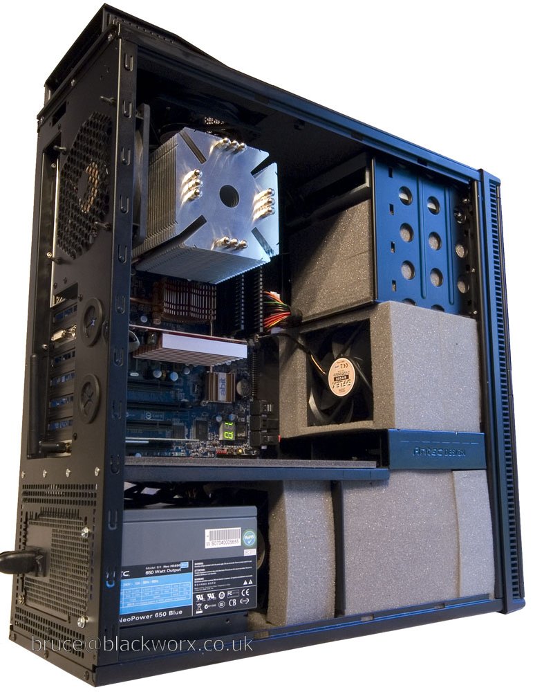
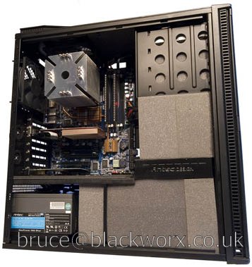
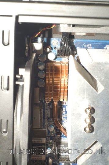
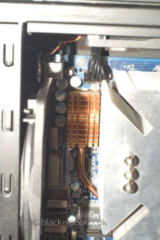
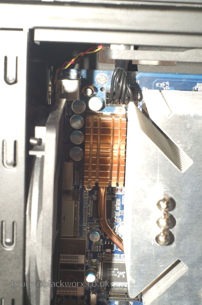
I like this - no cable mess in main chamber whatsoever.
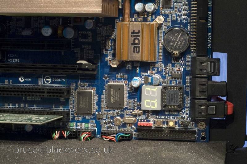
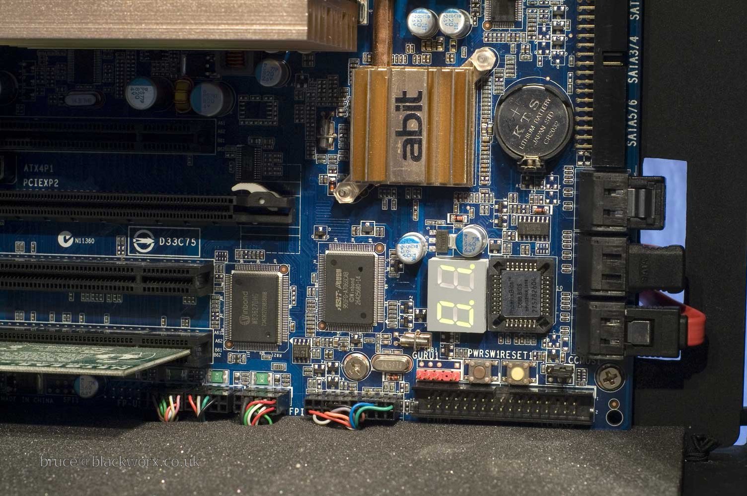
Also you can see the boltmod on the mobo heatpipe assembly. One of my missing pics showed how the mobo looked originally. The heatpipe assembly was twisted, didn't make any contact with half the PWM's and was sitting at an angle on the NB. The whole assembly was twisted and had to be flattened prior to remounting.

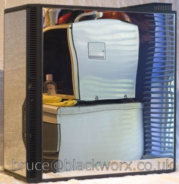
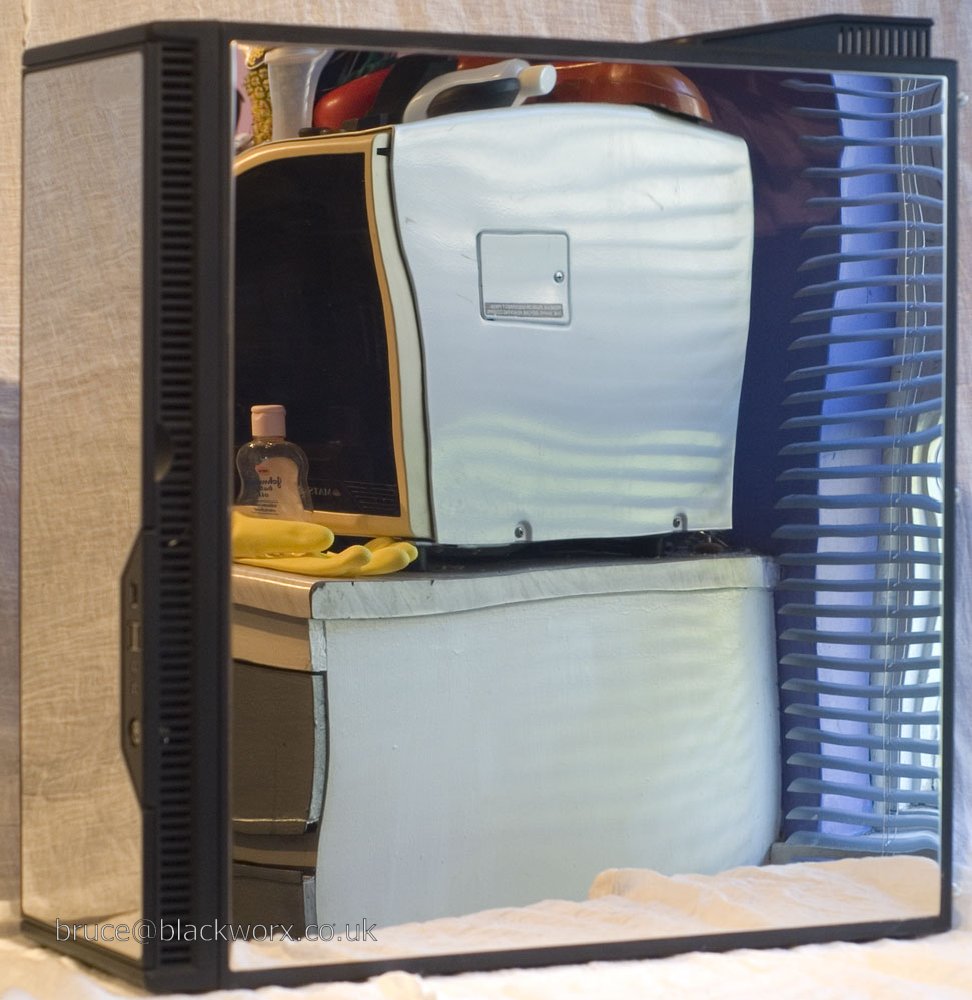
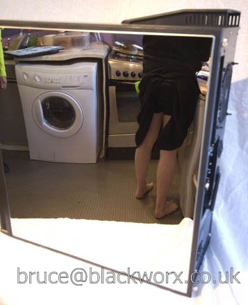
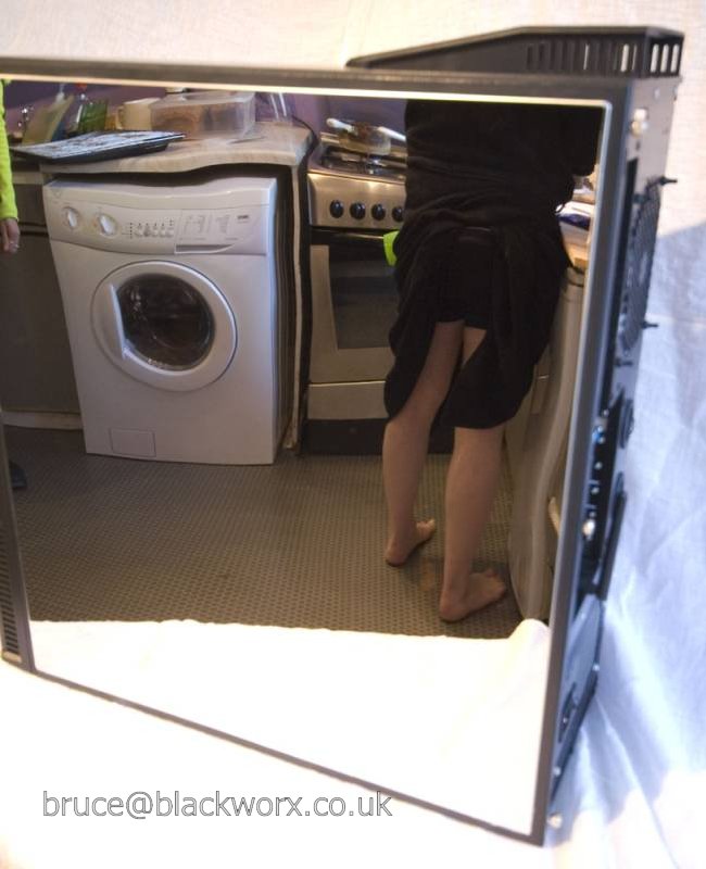
Look away now if you are of a nervous disposition. Oops, too late sorry.
(dressing gown: model's* own)
When these cases start coming on the market second hand I can envisage a sudden, er, surge, in eBay reflectoporn.
* for the record, the model is not me.
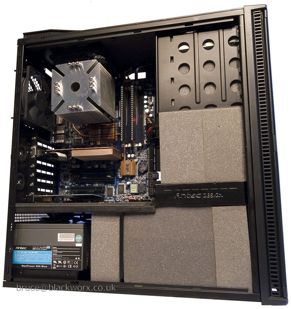
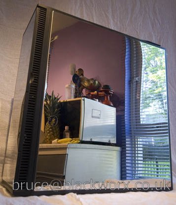
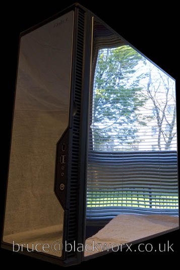
One last gratuitous "check out my shiny new pooter" shot.
During the build I hated this case. Before finishing the build I wasn't sure that I'd get on with the shiny finish, but I've been using it for a week or so now and I like it. Even though it looks like a miniature fridge.